Table of Contents
The Simple Question, and Why It Deserves a Long Answer
“Where should we install an oil-in-water sensor?” is one of the most frequent questions Shanghai ChiMay application engineers receive from refinery clients. The answer is rarely “at the outfall.” That single-point mindset — treat the discharge and hope the process behaves — is a legacy of the days when oil-in-water measurement was expensive, delicate, and reserved for compliance reporting only. Modern refineries operate multiple sensors across the water train, using the data to protect equipment, prevent excursions, and reduce chemical spend.
Below is a practical site map covering the five most valuable measurement points in a typical refinery water circuit, along with the sensor technology and range appropriate for each.
Point 1: Desalter Effluent Water Header
Downstream of the crude desalter, the wash water carries salts, sediments, and residual oil to the sour-water system. Continuous measurement here reveals emulsion carry-over before it reaches the biological treatment plant, where excess free oil can shock the biomass and trigger permit exceedances. Typical oil content ranges from 50 to 500 mg/L, with occasional spikes to several thousand mg/L during unit upsets.
Recommended technology. Turbidity-scattering oil-in-water sensor with a wide measurement window (0–1,000 mg/L). UV fluorescence is not the best fit here because heavy asphaltene content quenches the fluorescence signal.
Installation note. Mount the sensor on a bypass slipstream with automatic back-flush every four hours. The high solids load will otherwise foul the optical window within days.
Point 2: Sour-Water Stripper Bottoms
After stripping H2S and ammonia, the bottoms water still carries dissolved hydrocarbon in the 5–50 mg/L range. Reuse of stripper bottoms as desalter wash water is now common practice in modern facilities — in some plants it covers a substantial share of wash-water demand — and this reuse only works if the oil content is verified low. A sensor here provides the green light for reuse and the trigger to divert flow when contamination climbs.
Recommended technology. UV-fluorescence oil-in-water sensor with a low-range configuration (0–100 mg/L). Fluorescence responds specifically to aromatic hydrocarbons, giving a clean signal in this relatively clarified stream.
Installation note. Provide a sample skid with in-line filtration (100 μm) and temperature moderation to 40 °C. Continuous flow of 1–2 L/min keeps the optical cell clean.
Point 3: API Separator Effluent
The API separator is the primary gravity oil-water separator in most refineries. Its effluent, feeding the DAF (dissolved air flotation) unit or corrugated plate interceptor, typically carries 20–150 mg/L of dispersed oil. Measurement here quantifies the separator’s actual performance and warns of upstream slug releases.
Recommended technology. Turbidity-scattering or dual-technology sensor combining UV fluorescence and scattering. Dual-technology gives redundancy against interference from suspended solids.
Installation note. Install in a rising leg of pipe to avoid air entrainment. Retractable housings allow cleaning without draining the line.
Point 4: DAF or Induced Gas Flotation Unit Outlet
After secondary separation, oil concentration should be below 20 mg/L before biological treatment. A sensor here confirms the DAF is doing its job, catches chemical dosing errors quickly, and provides feed-forward information to the biological reactor operators.
Recommended technology. UV-fluorescence sensor with 0–20 mg/L range for high resolution in this cleaner stream.
Installation note. Mount in a small side-stream cell with a defined flow. This point often becomes the first-line KPI for the water treatment shift supervisor.
Point 5: Final Discharge (Outfall Compliance)
The regulatory-critical point. U.S. refinery outfalls are permitted under the NPDES program with limits derived from the ELGs in 40 CFR Part 419 — oil-and-grease allocations of 6.9 kg per 1,000 m³ of feedstock for any one day and 3.7 kg per 1,000 m³ as a 30-day average, with many permits adding concentration-based limits on top. For offshore produced water, 40 CFR 435.13 sets 42 mg/L for any one day and 29 mg/L as a 30-day average. In the North-East Atlantic, OSPAR Recommendation 2001/1 sets a 30 mg/L performance standard for dispersed oil in produced water. In China, GB 8978-1996 sets a 5 mg/L petroleum limit under its Class I (top-tier) discharge standard, and refinery discharges now fall under the tighter industry standard GB 31570-2015. Whatever the local regulation, the outfall sensor is the last line of defense before a violation.
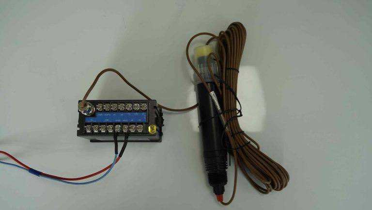
Recommended technology. UV-fluorescence Shanghai ChiMay oil-in-water sensor with certified linearity, tied into a redundant transmitter with 4–20 mA output plus Modbus RTU communication to the plant historian. Configure high-high alarms at 80 percent of permit limit to give operators time to react.
Installation note. Provide independent power and communication paths for reliability. Consider hardware redundancy — two sensors on the same line — for permit-critical service.
What About Bonus Points?
Beyond the five must-have locations, several optional points can add value:
- Ballast water treatment inlet at export terminals attached to the refinery.
- Slop oil tank suction to guide slop recovery scheduling.
- Cooling tower blowdown if hydrocarbon leaks from exchangers are a chronic concern.
- Storm-water separator outlet to distinguish rain-only events from process contamination.
Each of these can be justified case by case, and Shanghai ChiMay engineers can help build the business case using historical flow, concentration, and event data.
Common Mistakes to Avoid
Placing a single sensor at the outfall only. This makes compliance measurement possible but eliminates any chance to prevent exceedances.
Choosing UV fluorescence at high-solids points. Fluorescence is beautiful physics, but it fails when suspended solids scatter and absorb the excitation light. Match the sensor to the matrix.
Ignoring maintenance access. A sensor in an inaccessible location will be neglected. Retractable housings, valve isolation, and clear labeling matter as much as the sensor itself.
Skipping the calibration verification. Field calibration with a factory-blended oil-in-water standard should occur quarterly. Trend the results.
Assuming the sensor is a one-time buy. Optical windows, gaskets, and reference materials are consumables. Budget accordingly.
Data Integration
Modern refineries route oil-in-water data to the plant historian, the environmental compliance system, and often to a real-time optimizer. Shanghai ChiMay sensors support Modbus RTU, HART, and 4–20 mA outputs, giving integration teams multiple options. When paired with COD, pH, and conductivity sensors along the same water train, the oil-in-water signal becomes part of a comprehensive water-quality picture that supports pattern recognition and event forensics.
Closing Perspective
Where does oil-in-water monitoring belong in a modern refinery? Not just at the fence line. A well-designed sensor deployment covers five points from crude desalter to outfall, uses the technology matched to each stream, and delivers actionable data to operators long before a compliance excursion. Shanghai ChiMay works with instrumentation and reliability teams to design deployments that protect both the environment and the operating margin. The refineries that get this right recover the sensor network cost quickly and keep collecting the operating benefits for years.